

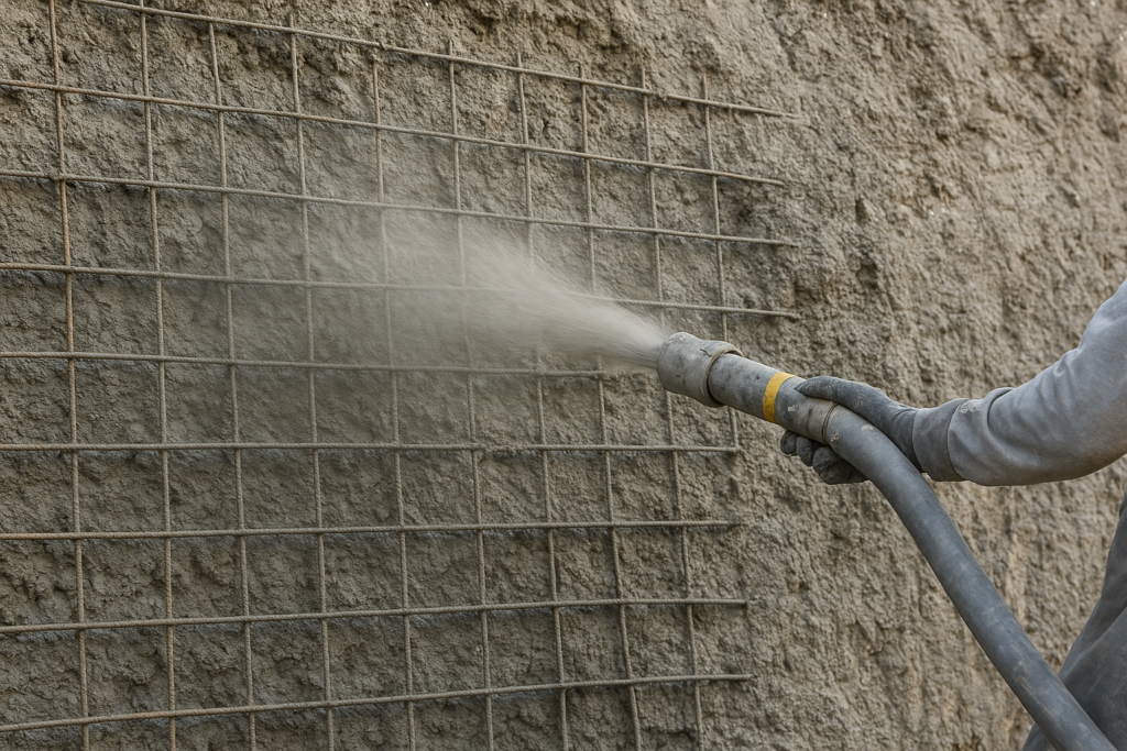
Usage of Weldmesh in Guniting: Reinforcing Strength and Stability
Table of Contents
ToggleWalk into any road tunnel under construction in the Himalaya, any underground metal mine in central India, or any 40-year-old canal being brought back into service, and you will find the same sequence: rock bolts, then a grid of steel mesh pinned to the face, then concrete fired at it from a nozzle.
That grid is welded wire mesh. It is the cheapest item in the sequence and the one most likely to be specified casually. It is also the item that decides whether the lining holds together after the first shrinkage crack appears.
This is a guide to the usage of weldmesh in guniting: what the mesh actually does mechanically, what Indian and international codes require of it, how to choose between GI and MS, and the fixing details that separate a lining that performs from one that spalls in five years.
What is Guniting?
Here is a distinction most specifications get wrong.
Shotcrete is the umbrella term. IS 9012:1978, the Indian code on the subject, defines it as mortar or concrete conveyed through a hose and projected at high velocity onto a surface, where the force of the jet itself compacts the material. Because the mix is relatively dry, it supports its own weight without sagging, even overhead.
Gunite is not a synonym. IS 9012 defines gunite explicitly as a trade name for the method of applying dry-mix shotcrete. So “guniting” is properly the dry-mix process, not the whole family. In Indian site usage the two words have collapsed into each other, and most tender documents use “guniting” for both processes. Knowing the difference matters when you are reading a foreign specification or arguing an interpretation with a client’s engineer.
The dry mix process
Cement and moist sand are mixed, fed into the gun, and blown through the delivery hose by compressed air. Water is introduced at the nozzle through a perforated manifold, under pressure, and mixes with the dry stream in the last few centimetres before impact.
The nozzleman controls water at the nozzle by hand and eye. That is the process’s strength and its weakness: it gives real-time control over consistency, and it makes quality a function of one person’s skill.
IS 9012 recommends trialling mixes generally in the range of 1 part cement to 3 to 4½ parts sand, and specifies that for hose lengths up to 30 m, air pressure at the gun should be 0.3 N/mm² or more, increasing by 0.035 N/mm² for every additional 15 m of hose and for every 7.5 m the nozzle is raised above the gun. Pressure discipline is not a detail. It is what drives compaction.
The wet mix process
Everything, including water, is mixed before entering the hose. Additional air is injected at the nozzle to lift velocity and improve the shooting pattern.
Wet mix gives better batching control, lower rebound and far better dust conditions, which is why it dominates modern tunnelling. Dry mix retains an advantage where placement is intermittent, where access is difficult, or where the job is small enough that a portable plant beats a pump.
A short history
The process came out of a cement gun developed by Carl Akeley in the early 1900s, originally to spray plaster onto museum specimen models. The trademark “Gunite” attached to that dry-mix method. Other trade names followed. ACI Committee 506 records that the generic term “shotcrete” was introduced by the American Railway Engineering Association in the early 1930s, and the American Concrete Institute adopted it in 1951 to describe the dry-mix process, later extending it to wet mix.
Where it is used
Anywhere formwork is uneconomical, impossible, or would take too long: tunnel primary support, mine roadways, slope faces, canal beds, thin repair overlays, water tanks, swimming pools, refractory linings and encasement of steel sections.
Terminology: correctly used, shotcrete = the family. Dry-mix shotcrete = the process. Gunite/guniting = the dry-mix method, originally a trade name. Sprayed concrete = the European term used in EN 14487. All four appear in Indian tenders.
Why Reinforcement is Essential in Guniting
Shotcrete is concrete. It shares concrete’s fundamental asymmetry: strong in compression, weak in tension, roughly an order of magnitude apart.
Four specific problems drive the need for reinforcement in sprayed applications.
Drying shrinkage is higher than in cast concrete. IS 9012 puts shotcrete’s drying shrinkage generally in the range of 0.06 to 0.10 percent, and notes this is higher than for most low-slump conventional concrete, which is placed in heavier sections with larger aggregate and leaner mixes. The code’s own conclusion: it will tend to give more shrinkage cracking and may require closer joint spacing.
There is a second, less obvious driver. Rebound is leaner and coarser than the original mix, which means the material that stays on the wall is richer in cement than what left the nozzle. IS 9012 states this plainly: the higher in-place cement content increases strength, but also increases the tendency towards shrinkage cracking. You cannot fix that with mix design alone.
Tensile weakness under ground movement. A tunnel lining is not a static object. Rock relaxes, convergence continues, blast vibration arrives from the next round. Plain shotcrete cracks and the crack goes right through.
Impact and abrasion. Mine roadways take scaling debris. Canal linings take silt-laden flow. Slope faces take rockfall. Unreinforced thin sections punch through.
Post-crack integrity. This is the real argument for mesh. Nobody expects the lining never to crack. The requirement is that after it cracks, the pieces stay attached to each other and to the substrate. Steel across the crack plane does that. Nothing else in the section does.
What is Weldmesh?
Weldmesh, or welded wire fabric, is a factory-made grid of longitudinal and transverse steel wires joined at every intersection by electric resistance welding.
The wires are drawn to a controlled diameter, laid out at fixed pitch, and each crossing is fused by passing a high current through the contact point while pressure is applied. There is no filler metal and no tying wire. The joint is a solid-state weld formed by the resistance heating at the interface.
The governing standard
IS 1566:1982 (Specification for Hard-Drawn Steel Wire Fabric for Concrete Reinforcement, Second Revision, reaffirmed 2004) is the Indian standard. Key points a buyer should know:
- The raw material is hard-drawn steel wire to IS 432 (Part 2).
- The fabric is classified as square mesh or oblong mesh.
- Mesh sizes, wire sizes and weights are agreed between purchaser and manufacturer. The code carries commonly used dimensions in its appendix, but it does not lock you into a catalogue. This is the clause that gives you room to specify what your section actually needs.
- Nominal mass is calculated from steel at 7,850 kg/m³, not from a weighbridge guess.
- An amendment to the standard allows the purchaser to demand a certificate that every welded intersection can withstand a shear load of not less than one quarter of the load needed to develop the smaller intersecting wire’s specified proof stress in tension.
That last clause is the single most useful procurement lever in the standard and almost nobody invokes it. Weld shear strength is where cheap mesh fails. A grid whose welds pop when you pull it round a rock bolt is not reinforcement, it is scrap in a roll.
Critically, IS 9012 clause 3.5 permits welded wire fabric conforming to IS 1566 as reinforcement for shotcrete. The mesh route is not a workaround. It is in the code.
MS Weldmesh
Plain uncoated hard-drawn or mild steel wire mesh. Bare steel, mill finish, sometimes lightly oiled. It relies entirely on the alkalinity of the surrounding concrete to protect it.
GI Weldmesh
Galvanized mesh. Zinc coating applied to the wire, most commonly hot dip to IS 4826 (Hot-Dip Galvanized Coatings on Round Steel Wires), which groups coatings into light, medium and heavy classes with defined minimum coating mass by wire diameter. The current edition covers wires from 0.200 mm to 10.0 mm.
Two production routes matter and buyers confuse them constantly:
- GI wire welded (pre-galvanized): wire is galvanized, then welded. The weld nugget burns off zinc locally, leaving small unprotected spots at every intersection.
- Welded then hot-dip galvanized: the finished panel goes into the zinc bath. Complete coverage including the welds. Costs more. Lasts longer.
For anything permanently exposed or in aggressive ground, the second route earns its premium.
Wire diameters and openings
Typical shotcrete mesh in Indian practice sits between 2.5 mm and 6 mm wire at 50×50 mm to 150×150 mm openings, with 3 mm at 75×75 mm and 4 mm at 100×100 mm being the workhorses. Heavier grids go into structural repair and thick linings.
The lower bound is not a preference. IS 9012 clause 8.3.1 fixes the minimum wire mesh spacing at 50 mm by 50 mm. Anything finer, and shotcrete cannot get through the grid to encase it. You get a screen, not reinforcement.
How Weldmesh Works in Guniting
Stress distribution
Concrete under a point load, or over a spanning defect, concentrates tension in a small zone. A welded grid at fixed pitch intercepts that zone regardless of where it forms, because the reinforcement is continuous and isotropic in the plane. Loose bars concentrate capacity at the bar; mesh spreads it across the panel.
Crack control, which is not crack prevention
Mesh does not stop cracks. It changes their character. Reinforced sections develop many fine cracks instead of a few wide ones. Total crack width for a given imposed strain is roughly conserved; the mesh redistributes it.
That distinction matters commercially, because fine distributed cracking is durable and a single wide crack is not. Crack width governs carbonation rate, chloride ingress and water leakage. Below roughly 0.3 mm, most crack-related durability problems become manageable. Above 0.5 mm you have a maintenance liability.
Bond and load transfer
Two mechanisms work together. Plain hard-drawn wire develops bond mainly through adhesion and friction along its length, which is modest. The welded cross wires supply the rest: each transverse wire acts as a mechanical anchor bearing against the concrete, and load transfers into the grid through those welds.
This is why weld shear strength is a structural property, not a QC nicety. If the weld fails, the anchorage mechanism fails with it and the longitudinal wire simply pulls out of the section.
Flexural performance
Mesh placed away from the neutral axis raises flexural capacity by supplying a tension chord. In a 75 to 100 mm lining, the placement window is narrow and the difference between mesh at correct depth and mesh flat against the rock is a large fraction of the section’s moment capacity. Every millimetre of lever arm counts in a thin section.
Toughness after cracking
This is the property that keeps tunnel crews alive. Once the shotcrete cracks, mesh holds the fragments in place and lets the lining continue carrying load in a ductile mode instead of shedding blocks. EN 14487 formalises this class of behaviour through energy absorption and residual strength classification for fibre reinforced sprayed concrete; the equivalent function in mesh-reinforced work is the same, achieved with a grid instead of dispersed fibres.
Durability
Steel in sound concrete is passivated by the pore solution’s high alkalinity. That protection has a shelf life. Carbonation moves the alkalinity front inward at a rate roughly proportional to the square root of time, and shotcrete’s higher shrinkage cracking gives carbon dioxide and chlorides a head start. Cover depth and coating are what buy you decades.
“Mesh does not stop cracks. It converts one crack you can see into twenty you cannot. That is the entire durability argument.”
Applications of Weldmesh in Guniting
Tunnel lining
Primary support in drill-and-blast and roadheader tunnels: shotcrete flash coat, mesh pinned to the face, rock bolts, further shotcrete to design thickness. Mesh spans between bolt heads and stops loose blocks. The International Tunnelling Association’s working groups on sprayed concrete treat mesh-reinforced shotcrete as established practice, with fibre reinforcement as the alternative where profile irregularity makes mesh fixing impractical.
Where the rock profile is rough, mesh fights you. It bridges the hollows, traps rebound behind itself, and creates the voids that show up on a hammer sounding. That is a real limitation and worth saying out loud.
Mining projects
Roadways, crosscuts, shaft stations and ore pass linings. Mesh plus bolts plus shotcrete is the standard ground support system in Indian underground metal mines. Mesh also does a second job here: it catches scaling debris between shotcrete applications.
Hill slope stabilization
Cut faces on hill roads across Himachal, Uttarakhand, Sikkim and the Northeast. Mesh is anchored with soil nails or rock dowels, shotcrete applied over it. FHWA’s soil nail wall guidance treats welded wire mesh facing as the standard construction facing for nailed slopes, with bearing plates transferring nail load into the mesh and shotcrete.
For hill road cuttings, IRC guidance on hill roads and slope protection is the governing reference in Indian practice, and site-specific geotechnical design should always precede a standard detail.
Canal lining
New lining and rehabilitation of existing channels. IS 9012 is specific here: where shotcrete goes against earth surfaces as in canal linings, the surface must first be thoroughly compacted and trimmed to line and grade. Skip that and the lining takes the subgrade’s settlement as a crack pattern.
Retaining walls
Facing for nailed or anchored walls, and thickening of existing walls that have lost section. Mesh is what lets you build a structural facing without formwork on a face you cannot reach from both sides.
Bridge rehabilitation
Soffit repairs, pier jacketing, abutment strengthening. Guniting places material overhead without shuttering, and mesh is what ties the new material to the old section and the exposed old reinforcement.
Concrete repair
Spalled slabs, delaminated columns, damaged industrial floors. IS 9012 clause 8.3.3 covers the fixing detail for repair work: reinforcement is fixed to existing masonry and concrete by wiring to nails driven into walls, and secured rigidly so that the vibration from deposition does not displace it. A mesh that shakes loose while you are shooting at it will be sitting somewhere unhelpful when the concrete sets.
Dam repair
Spillway surfaces, upstream face treatment, gallery linings. Large areas, difficult access, no realistic formwork option.
Railway embankments
Slope faces adjacent to track where a slip closes the line. Speed of construction is the deciding factor, and mesh plus shotcrete gets a face stabilised between traffic blocks.
Coastal structures
Splash zone repair on jetties, seawalls, breakwater elements. This is the environment where the GI decision is not a cost question. Chloride-driven corrosion in a splash zone is the most aggressive exposure in ordinary civil engineering.
Underground structures
Metro station boxes, cable tunnels, pump houses, basements. Mesh reinforced shotcrete does both temporary support and permanent lining depending on design.
Advantages of Using Weldmesh in Guniting
| Feature | Without Weldmesh | With Weldmesh |
|---|---|---|
| Crack resistance | Shrinkage strain concentrates into few wide cracks; full-depth cracking likely | Strain redistributed into many fine cracks; crack widths controlled |
| Structural integrity | Section loses continuity at first crack; blocks can detach | Fragments held across the crack plane; lining stays composite |
| Installation time | No fixing time, but higher rework and repair cycles | Fixing adds a shift per face; far less cutting out and re-shooting later |
| Uniform reinforcement | None. Capacity depends entirely on mix consistency | Factory-fixed pitch delivers the same steel per m² across the whole face |
| Labour requirement | Lower initially; higher over project life through repairs | Fixing crew required; no tying of individual bars, no bar bending yard |
| Concrete performance | Compression only. Effectively zero post-crack tensile capacity | Composite flexural and tensile capacity; ductile post-crack behaviour |
| Service life | Shortened by wide cracks accelerating carbonation and chloride ingress | Extended; fine cracks slow ingress, cover and coating do the rest |
| Maintenance | Recurrent patch repair, often within 5 to 8 years in exposed work | Planned inspection; intervention driven by exposure, not by first crack |
GI Weldmesh vs MS Weldmesh for Guniting
| Parameter | MS Weldmesh | GI Weldmesh |
|---|---|---|
| Corrosion resistance | Depends entirely on concrete cover and alkalinity. No reserve once carbonation reaches the steel | Zinc coating gives sacrificial protection; tolerates cracks, thin cover and carbonation for a defined period |
| Cost | Baseline | Typically 20 to 35% higher depending on coating class and route |
| Best applications | Temporary support, dry underground work, thick well-covered linings, short-design-life work | Coastal and splash zone, canal and hydraulic work, permanent slope faces, aggressive ground, thin sections |
| Life expectancy | Governed by cover and exposure. Adequate in benign, well-covered work; short in exposed thin sections | Zinc life scales with coating mass and exposure; adds years to decades before the steel begins to corrode |
| Maintenance | Higher inspection burden in exposed work; spalling repairs once corrosion starts | Lower over design life; the coating is the maintenance you paid for in advance |
| Strength | No difference. Both are governed by the base wire to IS 432 (Part 2). Galvanizing does not add tensile strength | Same as MS. The zinc is a durability measure, not a structural one |
| Surface finish | Bare mill steel; surface rust appears quickly in storage | Bright or matte zinc; handles storage and delays before shooting far better |
Recommendation
Use MS Weldmesh for temporary tunnel and mine support, dry underground applications with adequate cover, and thick structural linings where cover comfortably exceeds IS 456 requirements for the exposure class.
Use GI Weldmesh for anything coastal, anything carrying water, anything permanently exposed to weather, any thin section where cover is tight, and any structure where the cost of future intervention is high relative to the mesh premium. On a slope face above a live highway, the difference between MS and GI is a few rupees per square metre. The difference in the cost of going back is measured in lane closures.
How to Select the Right Weldmesh
Work through these in order. The section thickness usually decides more than anything else.
1. Concrete thickness first. Section thickness sets the placement window and therefore caps everything downstream. In a 50 mm flash coat, a 6 mm mesh cannot be placed with sensible cover on both faces. Match the mesh to the section, not to habit.
2. Wire diameter. Driven by required steel area per metre width and by handling. Thicker wire means fewer intersections to shoot through but a stiffer roll that will not follow an irregular face. On rough rock, thinner wire at a closer pitch conforms better and traps less rebound.
3. Mesh opening. IS 9012’s floor is 50×50 mm. Practical shotcrete openings run 50×50 to 150×150. Closer than the code minimum, and the grid screens the mix and builds a sand pocket behind itself.
4. Structural load. Temporary ground support is a different design case from a permanent lining carrying long-term rock load. Get the design case named in writing before you specify.
5. Exposure conditions. IS 456 exposure classes drive both cover and the GI decision. Marine, buried in aggressive soil, and constantly wet are the three that change the answer.
6. Corrosion strategy. Cover and coating are alternatives up to a point and complements past it. Where cover is generous, MS is defensible. Where cover is tight because the section is thin, coating carries the load. Thin section plus MS plus aggressive exposure is the combination that fails.
7. Project type and logistics. Panels or rolls. Rolls conform to curved faces and travel better to remote hill sites. Panels lie flatter and fix faster on regular profiles. Roll memory is a real site problem: mesh that wants to spring back will fight your fixers all shift.
Installation Best Practices
Most shotcrete failures are fixing failures. IS 9012 is unusually blunt about this: improper preparatory work is more often responsible for failures of shotcrete in repair work than any other single factor.
Surface preparation
Shotcrete must not be placed on any surface that is frozen, spongy, or has free water on it. Keep the surface damp for several hours before application. For repairs, remove all unsound material, chip until there are no offsets that would cause an abrupt change in repair thickness, taper all edges, and leave no square shoulders at the perimeter of the cavity. Clean exposed reinforcement free of rust and scale.
Fixing the mesh
Fix it rigidly. The code’s requirement for repair work is that reinforcement be wired to nails driven into the existing structure and secured so that vibration from deposition does not displace it. The same principle governs tunnel work through bolt plates and dowels. Loose mesh vibrates under the jet, and vibrating mesh creates voids on its blind side.
Clearance behind the mesh
IS 9012 clause 8.3.1 requires sufficient clearance around reinforcement to permit complete encasement. Minimum clearance between the reinforcement and the form or backup material ranges from 12 mm for a mortar mix with wire fabric up to 50 mm for a concrete mix with 16 mm bars.
Twelve millimetres behind the mesh is the number to hold. Mesh flat against rock is the most common defect in Indian shotcrete work, and it produces exactly the failure the code is trying to prevent.
Spacers and chairs
Use them, and offset them. IS 9012 warns that a continuous chair must not run directly underneath a reinforcing bar, because it will probably produce a sand pocket under the bar. The same logic applies to mesh.
Anchors
Bolt plates, dowels and pins carry the mesh and, in nailed slopes, transfer nail head load into it. The anchor pattern is a design output, not a site decision.
Overlaps
Wire mesh shall be lapped 1½ squares in all directions. That is the code, clause 8.3.2, and it is the single most ignored line in Indian shotcrete practice. A 100×100 mm mesh needs 150 mm of lap. Not “one square”. Not “some overlap”.
Where bars are lapped, do not tie them together. Separate them by at least 50 mm wherever possible, so the mix can get between them. Lap lengths for bars follow IS 456.
Cover
Minimum cover to reinforcement is as per IS 456, by exposure class. In a thin lining, position the mesh so cover and the 12 mm rear clearance are both satisfied. If they cannot both be satisfied, the section is too thin or the mesh is too heavy. Change one of them rather than hoping.
Shooting sequence
Start at the bottom for walls, columns and beams. The first layer must at least completely embed the reinforcement adjacent to the form. Hold the nozzle perpendicular, generally 0.5 to 1.5 m from the work.
When gunning through and encasing reinforcement, IS 9012 tells the nozzleman to do three things: hold closer, angle slightly off perpendicular, and run the mix a little wetter than normal without going so wet that it sloughs behind the bar. This drives plastic material behind the steel while preventing build-up on the front face. Get it wrong and the code’s own figure shows what you get: build-up on the face, a sand pocket behind, and a shrinkage crack forming at the weakened section.
Rebound
Rebound varies with position. IS 9012 gives the ranges: 5 to 15% for floors and slabs, 15 to 30% for sloping and vertical walls, 25 to 50% for overhead work. Mesh increases rebound because the wires themselves are hard surfaces to ricochet off.
Rebound must not be worked back into the construction. If it does not fall clear, remove it. Never salvage it into later batches.
Successive layers
Let the previous layer take initial set. Remove laitance, loose material and rebound by brooming. Sand-blast anything that has reached final set, clean with an air-water jet, sound the surface with a hammer for drummy areas, and cut out and replace any drummy area, sag or defect with the succeeding layer.
Curing
Keep surfaces continuously wet for at least 7 days, per IS 9012 read with IS 456. The code notes that good curing is particularly important precisely because shotcrete is thin, rough-surfaced and low-workability. Thin sections lose water fast and crack when they do.
Quality inspection
Gun test panels periodically, at least 30 cm square and 75 mm thick, and take cores or cubes for compression testing and visual examination. For preconstruction trials, panels should be not less than 75×75 cm and not less than 7.5 cm thick, with at least part of the panel containing the same reinforcement as the structure, so you can see whether sound shotcrete is being obtained behind the steel.
Sound every layer systematically with a hammer. IS 9012 requires continuous inspection by a qualified supervisor covering materials, forms, reinforcing, ground wires, equipment, application, curing and temperature protection.
And check the nozzleman. The code compares shotcrete quality to weld quality: it depends on the operator in the same way. Panel gunning is the accepted qualification test.
Common Mistakes to Avoid
Lapping one square instead of 1½. Creates a plane of weakness exactly where you cannot see it. Costs nothing to do right.
Anchoring at too wide a pitch. Mesh sags between anchors, ends up hard against the substrate at the sag point and floating near the surface at the anchor. Both wrong, in the same panel.
Using mesh finer than 50×50 mm. Below the code minimum the grid stops the mix from getting through. You get a rendered screen with a void behind it.
Shooting rusted mesh. Light surface rust is acceptable and is often argued to improve bond. Loose flaking scale is not. IS 9012 requires exposed reinforcement to be cleaned free of rust and scale. Mesh that has spent a monsoon in an open yard needs inspection before it goes on a face.
Wrong wire diameter for the section. A 6 mm mesh in a 50 mm lining leaves nowhere for cover. The mesh is not the problem; the specification is.
Insufficient cover. The most common cause of premature failure in exposed shotcrete. Steel at 8 mm cover in a coastal splash zone will corrode, and when it does it will spall the lining off. Cover per IS 456, by exposure class, every time.
Poor curing. Seven days continuously wet. A tunnel is humid, so people assume curing is automatic. A ventilated tunnel with a 3 m/s air stream across the face is a drying environment.
Working rebound back in. Contamination, wrong grading, partially hydrated cement. It fails every test the code cares about.
Key takeaways
- IS 9012 permits welded wire fabric to IS 1566 as shotcrete reinforcement. The mesh route is code-sanctioned, not a shortcut.
- Minimum mesh spacing is 50×50 mm. Minimum lap is 1½ squares in all directions. Minimum clearance behind mesh is 12 mm for mortar mixes.
- Shotcrete shrinks more than cast concrete (0.06 to 0.10%) and rebound makes the in-place mix richer and more crack-prone. Mesh manages the consequence.
- Weld shear strength is a structural property. IS 1566’s amendment lets you demand a certificate for it. Use the clause.
- GI vs MS is a durability decision driven by exposure and cover, not a strength decision. Galvanizing adds no tensile capacity.
- Curing for 7 days and hammer-sounding every layer catch more defects than any amount of cube testing.
Why Contractors Prefer Weldmesh Over Traditional Reinforcement
Speed. A roll of mesh covers in minutes what a bar crew ties in hours. On a tunnel face with a fixed cycle time, that is the whole argument.
Labour cost and skill availability. Bar bending and tying at height, in a tunnel, or on a rope-access slope face require skilled labour in conditions where such labour is expensive and scarce. Mesh fixing requires fewer people and less exposure time.
Uniformity you can audit. Factory pitch means the steel area per square metre is what the drawing says, across the whole face. A tied grid depends on whoever tied it, at hour nine of a shift, in a headlamp beam.
Fewer failure points. Every tie in a hand-tied grid is a potential slip during shooting. Welded intersections do not slip.
Less wastage. Mesh is cut to the face. Bar comes in stock lengths and generates offcuts that end up as site scrap.
Handling. Rolls go where cut bar cannot: up a slope by hand, round a curve, into a heading on a single trip.
Programme certainty. This is what actually decides it. Faster fixing compresses the cycle, and on a tunnel or mine drive the cycle is the project. Everything else is a rounding error against advance rate.
None of which makes mesh the universal answer. On highly irregular rock profiles, mesh bridges hollows, traps rebound and slows the shooting itself, which is why steel fibre reinforced shotcrete has taken share in modern tunnelling. Mesh wins on regular profiles, on prepared faces, in repair work, on nailed slopes, and wherever a defined grid geometry is part of the design. Choose on the profile, not on the brochure.
Frequently Asked Questions
For shotcrete, largely yes. IS 9012 clause 3.5 permits welded wire fabric to IS 1566 as reinforcement, and clause 8.3 states that reinforcement may consist of either round bars or welded wire fabric. The code prefers small bars where bars are used, calling 16 mm the normal maximum, precisely because large bars are hard to encase. Mesh sidesteps the problem. For designed structural elements where a specific bar arrangement carries calculated load, mesh supplements rather than replaces. The design case decides, not the product.
There is no universal answer, and anyone giving you one is selling stock. The floor is set by code: IS 9012 fixes minimum spacing at 50×50 mm. Common Indian practice runs 3 mm at 75×75 mm and 4 mm at 100×100 mm for tunnel and slope work. Section thickness, required steel area and rock profile decide. IS 1566 leaves mesh sizes to agreement between purchaser and manufacturer, so the right specification is the one your section needs.
Better at resisting corrosion. Identical in strength. The base wire is the same under IS 432 (Part 2); zinc adds no tensile capacity. GI earns its 20 to 35% premium where exposure is aggressive, cover is tight, or future access is expensive. In dry, well-covered, temporary underground work, MS is the correct engineering answer and GI is a waste of money.
Design decides, from the ground conditions and the load case. What the code sets is the constraint chain: minimum cover per IS 456 by exposure class, plus minimum clearance behind the mesh (12 mm for a mortar mix with fabric), plus the mesh itself. Work backwards from those and you get a floor on thickness for a given mesh. Indian tunnel and slope work commonly runs 50 to 150 mm in one or more layers.
It is standard practice, in India and internationally. Mesh plus rock bolts plus shotcrete is the conventional primary support system, and mesh-reinforced sprayed concrete is treated as established practice in ITA guidance. The alternative on irregular profiles is steel fibre reinforced shotcrete, which trades the grid for dispersed fibres and avoids the fixing time and the rebound shadow.
Yes, both for shotcrete facing on nailed and anchored walls and for thickening existing walls that have lost section. FHWA’s soil nail wall guidance treats welded wire mesh facing as the standard construction facing, with nail head plates transferring load into the mesh and shotcrete. Facing design follows the wall design and needs a geotechnical engineer.
There is no single number, and treat any supplier who gives you one with suspicion. Zinc consumption rate depends on coating mass (IS 4826‘s light, medium and heavy classes give different minimums by wire diameter), exposure, and whether the mesh is encased in sound alkaline concrete or sitting behind a crack. Buried in good concrete with adequate cover, zinc is barely consumed and the mesh outlives the structure’s design life. Exposed in a coastal splash zone at light coating, it is a matter of years. Specify the coating class against the exposure and the design life. That is the honest answer.
Shotcrete is the general term for pneumatically projected mortar or concrete. Gunite, per IS 9012 clause 2.3, is a trade name for the method of applying dry-mix shotcrete. So all guniting is shotcrete; not all shotcrete is guniting. Indian tender language uses them interchangeably. We recommend to read the process clause, not the heading.
Two reasons, both in IS 9012. Drying shrinkage runs 0.06 to 0.10 percent, higher than most low-slump conventional concrete because shotcrete is placed thin with finer aggregate. And rebound is leaner and coarser than the mix, so the in-place material carries more cement than what left the nozzle. Higher cement means higher strength and higher shrinkage. Mesh is how you manage the outcome.
Yes. Rebound already runs 15 to 30% on vertical walls and 25 to 50% overhead per IS 9012, and every wire adds a hard surface for material to ricochet off. It is a real cost, and it is why nozzle technique around reinforcement (closer, slightly angled, marginally wetter) is a specified procedure rather than a preference. Budget the rebound and train the nozzleman.
Conclusion
Weldmesh is the cheapest structural component in a shotcrete lining and the one that decides whether the lining behaves after it cracks. It converts a brittle section into a ductile one, redistributes shrinkage strain into fine cracks that concrete can live with, holds fragments across the crack plane, and gives you a factory-guaranteed steel area per square metre that a hand-tied grid never will.
The code has done most of the thinking already. IS 9012 permits mesh to IS 1566, sets 50×50 mm as the minimum spacing, requires 1½-square laps in all directions, demands 12 mm clearance behind the fabric for mortar mixes, and asks for 7 days of continuous wet curing. IS 1566 gives you the right to demand certified weld shear strength. IS 4826 provides graded zinc coatings to match the exposure level. Most site failures are not exotic. They are one of these clauses ignored.
The part that is not in the code is the specification itself: wire diameter against section thickness, opening against rock profile, coating class against exposure and design life, roll against panel for the access you actually have. Those choices are project-specific, and getting them wrong is expensive in ways that only show up years later.
MM Industries has manufactured GI and MS welded wire mesh from Raipur since 1995, supplying infrastructure, mining and tunnel contractors across Pan-India. If you are working through a shotcrete specification and want a second opinion on wire diameter, opening, coating class or panel format for your section and exposure, our technical team will work through it with your drawings. Send us the section detail and the exposure condition, and we will tell you what we would specify and why.